Hi all,
I'm used to working with Codesys and I can't find my way fully around Mervis yet :)
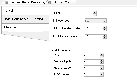
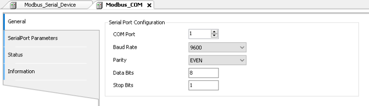
So I am trying to read out some PPM CO2 readings from a Modbus RTU transmitter
-
Datasheet: http://downloads.epluse.com/fileadmin/data/product/ee870/BA_EE870_e.pdf
-
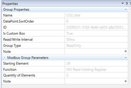
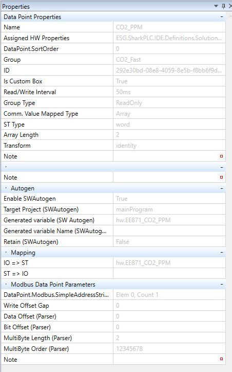
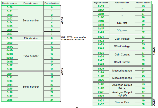
I'm trying to read out the CO2 fast parameter: Address: 29 + 30
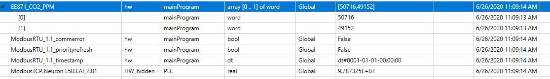
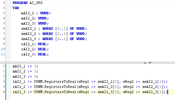
It seems I can read out some values, but I have to combine them into a REAL, in Codesys I use UNION to combine both words (and swap them) into a REAL.
What is the easiest way to achieve this within Mervis?
Thank you.
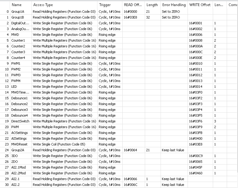 -> Line 27-30
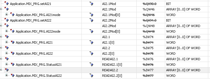
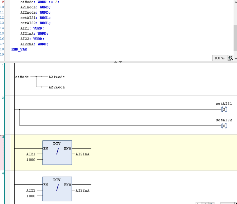 -> Rank 3/4 (placeholder for conversion from input to what I need)