@zdenek_jotio Success!!
I've changed your inject node to "1" instead of "1_01" and it's worked.
Finally getting somewhere.... Changing the nodes is working on all examples now
Brilliant, thanks for the direction
L
Posts made by lessmann
-
RE: Switching output or relay onposted in Node-RED
-
RE: Switching output or relay onposted in Node-RED
@zdenek_jotio I imported your example but it's not switching.
This is really frustrating, the Unipi responds as expected through the Evok interface but nothing is working with NodeRed. -
RE: Switching output or relay onposted in Node-RED
@WesleyFranken
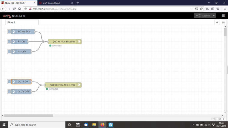
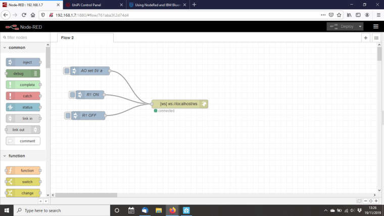
I've gone back to the installation instructions and tutorial and trying to follow the initial basic example given but again it does not seem to do anything.This is the flow.....
[{"id":"a3c2ed71.5c3d1","type":"websocket-client","path":"ws://127.0.0.1/ws","wholemsg":"false"},{"id":"c7a9d1f1.38563","type":"websocket out","name":"","server":"","client":"a3c2ed71.5c3d1","x":643,"y":272,"z":"2b1b35ba.d4e4ca","wires":[]},{"id":"80afc33f.7f504","type":"inject","name":"R1 ON","topic":"","payload":"{\"dev\":\"relay\", \"circuit\":\"1\", \"value\":\"1\"}","payloadType":"string","repeat":"","crontab":"","once":false,"x":363,"y":199,"z":"2b1b35ba.d4e4ca","wires":[["c7a9d1f1.38563"]]},{"id":"3964a515.c69b5a","type":"inject","name":"R1 OFF","topic":"","payload":"{\"dev\":\"relay\", \"circuit\":\"1\", \"value\":\"0\"}","payloadType":"string","repeat":"","crontab":"","once":false,"x":357,"y":273,"z":"2b1b35ba.d4e4ca","wires":[["c7a9d1f1.38563"]]},{"id":"aa9c56df.5563a8","type":"inject","name":"AO set 5V a","topic":"","payload":"{\"dev\":\"ao\", \"circuit\":\"1\", \"value\":\"5\"}","payloadType":"string","repeat":"","crontab":"","once":false,"x":363,"y":114,"z":"2b1b35ba.d4e4ca","wires":[["c7a9d1f1.38563"]]}]....and this is the flow example
-
RE: Switching output or relay onposted in Node-RED
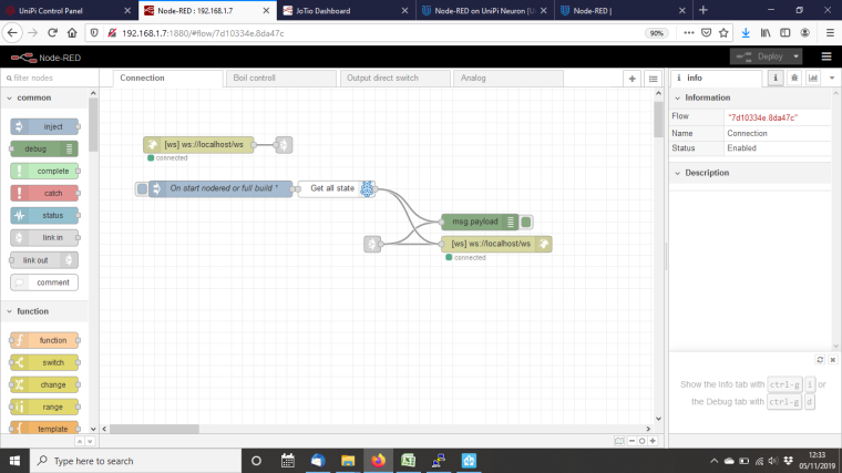
Are we sure that the "local host" is connected to the Unipi? It says "connected" in Node Red
-
RE: Switching output or relay onposted in Node-RED
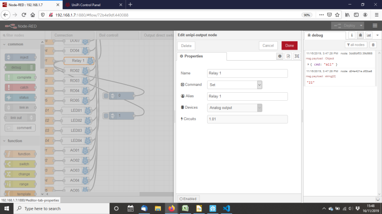
As the Evok can't be changed I must be naming the Relay incorrectly on the Node Red side.
I have attached Inject nodes into a "Relay 1" as you suggested and the screen print is below but it's not doing anything
-
RE: Switching output or relay onposted in Node-RED
@wesleyfranken I'm obviously a sucker for punishment but I have a replacement Unipi1.1 and it's set up and ready to go. Not that sure if I am, I don't think I like Node Red very much. I do not find it very intuitive.
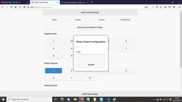
Anyway I am trying to understand what you were saying about configuring the I/O in Evok. Below is my configuration page but I can't change any of this...
-
RE: Switching output or relay onposted in Node-RED
@wesleyfranken my evok relay did not look like that and when I tried to write in the "alias" field I would get an error. Unfortunately I can't check this now as I have accidentally broken my unipi.
In an attempt to tidy up the dinrail I rewired the power and connected it to the wrong (24v) supply by accident.
Maybe I did it on purpose because it was causing me such a headache 😂Thank you for your help on this. I'll let you know when or if I get a replacement.
-
RE: Example UI flow not workingposted in Node-RED
@wesleyfranken I feel like I'm trying to learn chinese here!
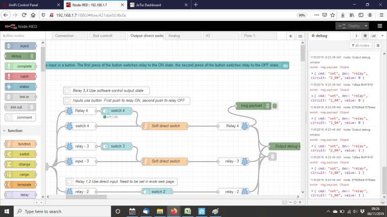
I have changed the flow to "Relay 4" and at least now when I select "switch 4" it indicates an "on" (whatever that means) but the relay is not switching?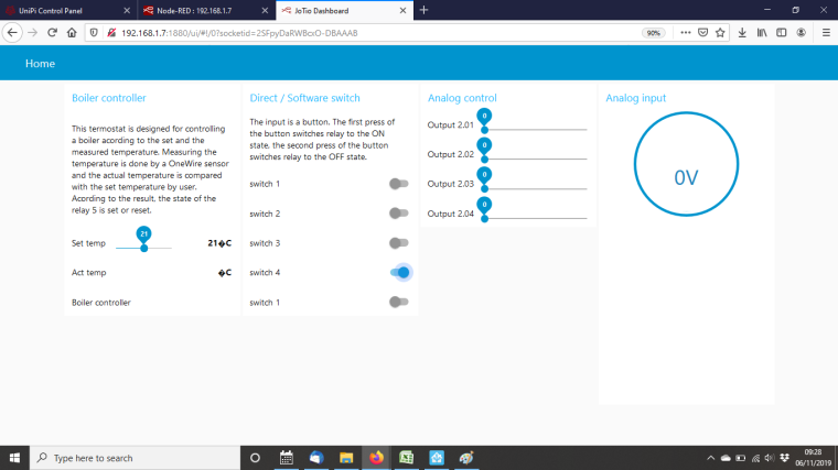
-
RE: Switching output or relay onposted in Node-RED
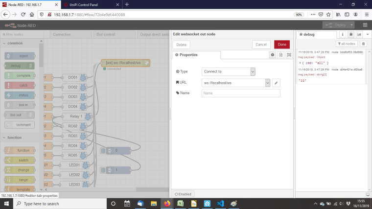
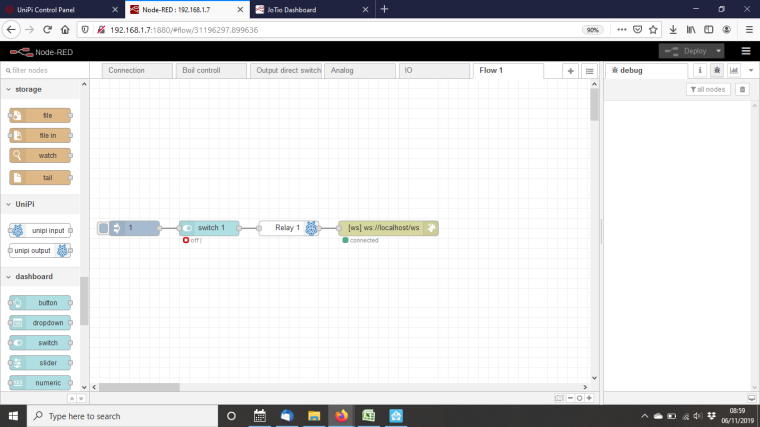
@wesleyfranken I've imported your flow into Node red thanks but I have no idea what to do with it at this stage.
I've named the Relay 1 as it is name in Evoke and added a simple "1" into an inject node but this is not triggering the relay?
Infact it seems to switch it off according to the screen print below.
-
Example UI flow not workingposted in Node-RED
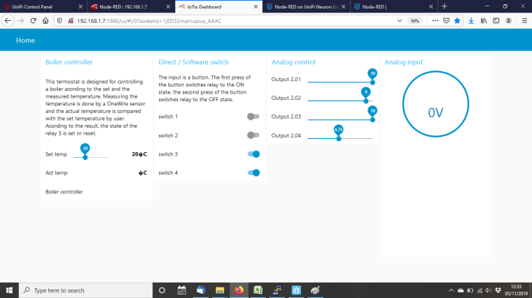
I've followed the OS instructions and imported the example demo flow. The UI inputs and outputs are not creating any physical changes on the unipi, how can I trouble shoot this?
https://kb.unipi.technology/en:sw:03-3rd-party:nodered:installation-neuron
The connections claim to be connected
-
Switching output or relay onposted in Node-RED
I am relatively new to Node-red but I think I have grasped the basics.
I am however struggling to get to grips with how to implement it on the Unipi, I have for example an mqtt msg which I am hoping to switch a relay on/offHow do I do this?
I've tried in several ways with no luck....To trouble shoot this I'll simplify it to the problem I'm having
I'll try simply to switch one of the relays using an inject node for example, how do I get the Relay or output to switch?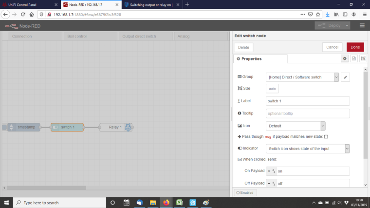
Is there a tutorial or guide to getting set up that I can follow?
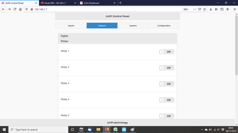
I do suspect that I may have an installation error as when trying out the boiler control UI example from the instructions none of the outputs react to UI inputs
-
RE: New Build Homeposted in Installations
Thanks Martin.
I would be grateful for your advice on the following hardware choice.
I have a rough estimate of what I/O's I'll need and the hardware required to cover that initial demand, now my query is this:
Is it better to have a small PLC with many Extensions or a large PLC with only a few Extensions? The advantage of the smaller PLC being that less can go wrong with the PLC which is the most critical item and should a relay break for example it would be simpler to exchange an Extention rather than a the PLC. Also there will only be local disruption instead of the whole system going down if anything malfunctions. The only downside is that I suspect the smaller PLC route will cost more.
I guess I've really answered my own question there....
Regarding the RS485 connection, I recall the documentation stating that a maximum of 6 Ext.'s can be connected to one BUS, please ignore my ignorance but is one BUS one RS485 connection?
In other words if I have 2 x RS485 connectors i can in theory connect 12 Ext.'s?
-
RE: New Build Homeposted in Installations
When it comes to expanding the I/O’s, and instead of using the Extensions, is it possible to have multiple PLC’s to increase those or will I have to access each PLC individually? Is this where the Modbus Master/Slave setup comes into play?
-
RE: New Build Homeposted in Installations
Thanks Martin
The lighting will be 24v led strips with maybe a handful of spotlights.
I think the only solution is to buy one of the PLC’s and start playing with it. For a newbie in the PLC market there really is very little documentation online to get one started. I have been making things with arduino’s and raspberry pi’s for a couple years now and if you are relatively tech savy and willing you can teach yourself but this wealth of knowledge is lacking when it comes to PLC’s...Thanks for the heads up on the axon-s605 but like you say it looks like a bit of a challenge at this stage. I’ll keep it in mind once I’ve mastered the basics!
I’m a long time user of Home Assistant and very much want to make HA the interface for all the control and automations in the new house. I’m surprised there isn’t a bigger overlap between the unipi and home assistant community. Maybe we can remedy that in the near future.... -
New Build Homeposted in Installations
I am about to start a new build house and want to build the smart home installation around the Unipi Axon. I’m pretty confident that most requirements will be covered, the only thing I’m less sure about is the dimming circuits, especially RGBW dimming. All the lights will be 24v LED and there is only one circuit that is RGBW, the rest are simple white light.
Basic Requirements:
Lights – Dimming= 10 ; Switched= 25
Sensors – Motion= 16 ; Temp &Humid= 8 ; Light= 6 ; Window cont.:= 7
Blinds= 6
UFH zones= 5Unipi Hardware:
Unipi Axon L505
Unipi Ext. xS50
1 Wire 8 Port hub
Power 24V 1.5AWhat would you guys recommend for dimming circuits?
The documentation claims the Axon range is Dali compatible but I’m not sure what hardware would be required to get this set up.
I found this 8ch LED Dimmer (0-10V, DMX, Modbus) which I think would be manageable through the Axon AO’s but this is no longer available.
https://www.tindie.com/products/NickB/8ch-led-dimmer-0-10v-dmx-modbus/
Would something similar work?
Maybe something like this from anigmo?
https://www.anigmo.com/store/product_info.php?products_id=142None of these cover the rgbw circuit though....