Unipi 1.1 how to use analogue output - PWM?
-
I am struggling to program analogue outputs in simple mode. Rather than to bore you with the long story of how I failed; is there anyone who could say how it is done?
I want to drive a PWM circulation pump (1-10V, 100Hz) to respond to a 1Wire temp reading so that the pump modulates from 0 to 100% in the temp range from 72 to 82 degrees.The pump should run at 100% at temperatures higher than 83.
I have found the wiring diagram in the step by step manual and my unipi is wired accordingly. I just cannot seem to give it the correct instructions...
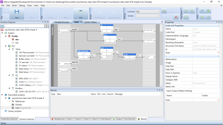
A screenshot of the main program in Mervis showing variables, the appropriate library box and its proper parameters (the only one labeled PWM is only for unipi 1.0 - or am I wrong?), and any required conversions from real to int would be very much appreciated.
-
@karel505 So is it a PWM controlled pump or analog output driven pump by 0-10V? Also I am missing the screenshot... Regarding the application, check the B80 Two-point function
-
@tomas_hora
Thanks for your reaction.B80 box looks just right
It is a wilo pwm controlled central heating circulation pump.
Perhaps I was unclear: I was hoping you might send me a screenshot of correct mervis code for this situation.
But it seems to be working ok now - thanks for your help -
I was too quick with the previous note.
With the B80 box, I can write the desired value to AO01. This value fluctuates as expected, responding to temp data. But when I monitor the resulting value on AI01 (using the wiring you suggest in the step by step manual) the actual output remains 4600 millivolts regardless of the input.
Also it seems not to deliver a PWM signal as far as I can tell.
Do I need another dialogue box to generate a PWM signal on AO01? I can see the B87 box, but that appears to be for Unipi 1.0 exclusively.
-
You need to use the AI1, the AIO input only rises up to ~4v. It's intended primarily for measuring resistance via a feedback loop with the AO1.I had a look at your screenshot and you are using the AI. The AIO is a separate input used for self-measurement of the AO, which is why I was confused.
-
@TomasKnot
thank you Tomas,
I will try that. But it does leave me puzzled. Are you saying I am reporting the wrong output in Fupla? I am using AI1 to show the output - is that not what you are suggesting?You say that AO is the wrong output to use, is AI1 actually an output (i assumed that the acronym stood for Analogue Input 1).Will the fupla program that I sent a screenprint of generate a PWM signal after changing the output?
Do i need to provide external 12V or is the 12V supplied by the unipi sufficient to drive 1 pump (it dissipates only a few mA)?
So is there a need to revise the diagram in de step by step manual, it clearly points at AO as the analogue output to use? -
You should use external supply to drive any device that requires significant current, the AO is only for control signals.
edit: Have a look at the following topic for an example: https://forum.unipi.technology/topic/643/digital-in-voltage/5
-
@TomasKnot
Thanks for your replies. I have hooked up external 12V supply and getting better values on AI1. That part now makes sense.
But my PWM pump is still not behaving as expected. It runs full speed at AI1 value of 1500 and below. It goes in standby at values 1500 and above.The pump datasheet indicates very forgiving signal requirements, 3 to 24 volt, duty cycle 0 to 100 % , 100 to 5000 hz (1000 hz nominal), signal power dissipation less than 5mA.
Is there any way I could adjust the PWM frequency, before I give up, I would like to deliver the signal it is nominally expecting (10V, 1000Hz, 50% PWM) and see what happens.
And can you please confirm that my fupla picture above in fact generates a PWM signal on AO in the first place.
PS
I saw your Axon range - very nice to see new range of PLC - congratulations! -
The UniPi 1.1 analog output uses a filter to transform the PWM into a continuous voltage. It's unfortunately not possible to extract the PWM signal itself without soldering a bypass for the low-pass filter.
It is possible that you can simply use variations in the voltage to regulate the pump, as it often is in practice equivalent to PWM control, but if the pump requires true PWM the UniPi 1.1 is not capable of it as stock.
The Neuron is capable of true PWM, but unfortunately the UniPi 1.1 is not without such a modification.
-
@TomasKnot
Thank you, that is disappointing, but very clear, and it explains what I am seeing.I also have a EMO-AO4/12 extension board; does it have the same problem?
-
I believe so, yes. Normally PWM and analog outputs are separate functions handled by different outputs, but UniPi 1.1 does not have PWM support unfortunately. The fact that the analog output is PWM-based is coincidence, though as I described above it could be turned into a non-analog PWM output with a few hardware modifications (though these would void warranty).
On Neuron you would use an analog output toggled by a digital (transistor) output to create the PWM signal, but as UniPi 1.1 only has relay-based (rather than transistor-based) digital outputs this is not going to be possible, as they cannot toggle with anywhere near the required speed, and have a maximum number of state changes due to their physical nature anyway.
The main advantage of relay outputs is they can handle orders of magnitude higher voltage and current, which is why the larger Neuron models have both (S103 only has transistor outputs).
-
@tomasknot
Thank you,Sorry for repeating a question, but I want to be sure that I understand your reply before I start modifying the unipi board.
On the EMO-AO4/12 extension board there are 4 analogue out connections that appear to be fully wired. The arrangement seems similar to the one on the Unipi 1.1 main board.
But there are an additional eight Analogue outputs provided as pinout connections. They look like direct pinouts; on the EMO board I see nothing indicating the presence of a low pass filter. Could that be correct, or are you saying that these eight have the same integrated smoothing circuit converting the PWM signal to a steady voltage?
-
Yes, these are direct pinouts. It depends on the specific type of extension board, but for the EMO-AO4 you are right.
Regardless the problem is the opposite - rather than the PWM filter being the issue, it is a potential solution. In other words - if you bridge the filter (or use the adjacent jumper available on some boards) you can get direct PWM out, that is in place of the original output. You will have to play with the output control values to get the right output frequency though. This is not possible with the EMO-AO4 extension, as it is a direct analog pinout, as you have correctly surmised.
Note that this is an unsupported modification, but we do have one relatively large-scale customer who makes use of it. It is up to you if you wish to take the risk of using it.
-
@tomasknot
Aha, thanks, that is very helpful. In that case,
Could you please share a picture of the required bypass on the Unipi board?