Mervis PWM connection to Meanwell driver
-
Hi,
I'm struggling to program mervis to control a meanwell pwm driver.
I have connected it to the DO_1.01 and it's not connected to the FBD.
Reading the driver specifications it supports a frequency of 100Hz and so i've set the PWM_prescale to 4799, the PWM_cycle to 100, and the T to 10ms as you can see in the following image: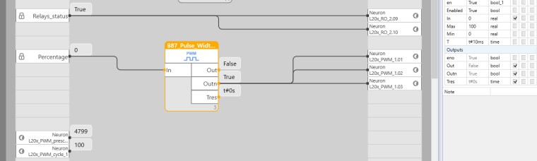
Changing the value of the percentage makes no diference on the light intensity.
Can someone point me in the right direction?
Thanks in advance
-
@n1lp0int3r You do not need to use the block, just write a proper value to the PWM variable instead. The value of PWM variable can be from zero to the value of PWM cycle, so in your case 0-100 which will equal to % of the PWM being in a HIGH state.
-
Hi @tomas_hora,
I've tried that before and got the same result.
Is it possible i need a pull down resistor?Thanks
-
@n1lp0int3r We are not quite sure about how it should be connected in order not to damage any of the electronics. So a couple of questions:
- How did you do the wiring?
- Is there a voltage between the DIM+ and DIM- clamps when everything except the 230V is disconnected?
Also make sure the the value of DO is se to 0.
-
@tomas_nora I've connected DIM- of the driver to the DOGND of the unipi and the DIM+ of the driver to the DO1.1 of the unipi.
Yes with the 230v on the AC input of the driver it outputs 10V (DC) on the DIM wires.
I've followed the names that are present in this schematic of the driver:
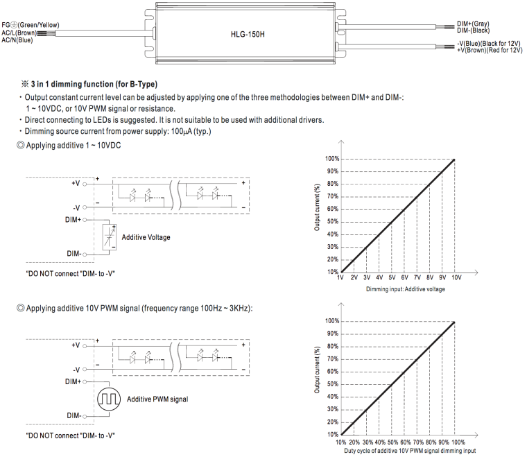 schematics.png
Thanks in advance.
-
Hi,
Looks like all it was needed was a reboot. After the reboot everything started working fine.
I'll leave the project image for future reference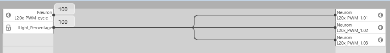
Just as a side note use 100 for the cycle. 255 (the default) with my drivers makes the light flicker when i set values between 0 and 255.
Thanks for all the help.