sedtronic 1 wire cabeling
-
Hi,
I just received the sedtronic sensors. Thanks for the quick delivery!
Now I have to make cables. My existing temp sensors, which came with unipi, have only 4 lines and work perfectly on my unipi 8 port hub. On your web site you recommend 6 lines (always two per contact). This is different to the temp sensors plugs I already use. Please let me know how the contacts are on your DS18B20 as a guideline for the new cables. -
@juntiedt I believe that this link will answer your question. If not, let me know: https://www.unipi.technology/hardware_documentation/1-wire-network-46
-
Hi Tommas,
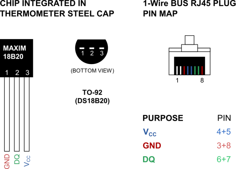
actually not. This shows the one with 6 wires. If you look at your DS18B20, which I got from you a year ago, it has only 4 wires in the plug. Have a look at it. This is different to the picture on your link with two wires for Ground, Data, 5 Volt.
-
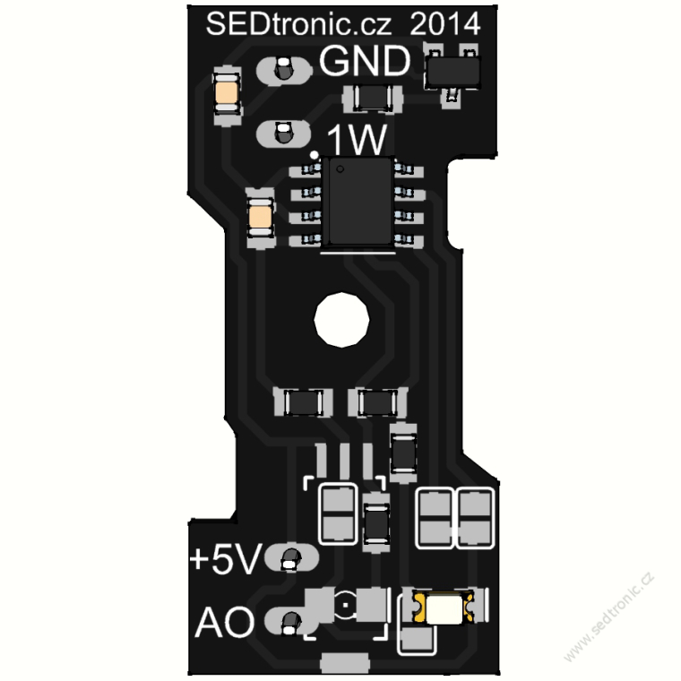
On the right-hand side there are six pins which you can use as guidelines for cabling - they connect to the pins as in the bottom picture, with guidelines printed on the chip. DQ is 1W, and AO does not need to be connected; it's for external measurement of the resulting current, is so desired for some reason.
The reason the lines are doubled is to maintain continuity when multiple sensors are connected to the same line. Strictly speaking only 4 may be necessary, but 6 are preferable
-
ok thanks.
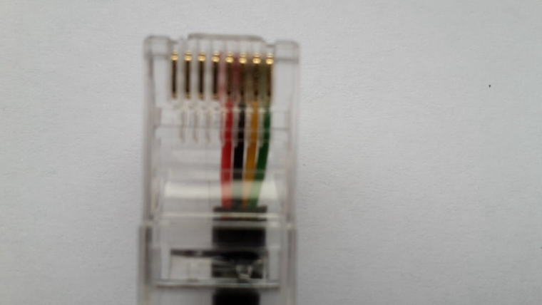
So if you have 4 wires as on the DS18B20 than green is ground, yellow and blue is DQ and red is 5 Volt. do You agree? -
Can you send us a photo of your cabling? It's a bit hard to imagine what it looks like.
-
-
It looks like the cabling is correct; if you cable it the same way it should work, yes.
-
More detailed instructions from my colleague in hardware development:
From what I understand you are trying to connect a 1Wire unit for humidity and temperature measurement into a 1Wire hub, which also has a number of our 1Wire thermometers connected to it.
For cabling our 1Wire thermometers we use two data carrier wires, which are connected as shown for sensor 18D20. The internal connections inside the 1Wire hub are then arranged such that after connecting our 18D20 1Wire thermometer the next port in the hub is physically connected to the same 1Wire line.
For this reason you should crimp the conductors into the RJ45 connector such as it is done for our 1Wire thermometer, and on the side of your device you should connect the cable marked GND in the schema above to the GND connector, 5V to the 5V connector and data conductors to the 1W connector. You can use the same cabling schema for connecting a 1Wire sensor directly into the Neuron PLC as well.
Hope it helps!
-
Hi Tomas,
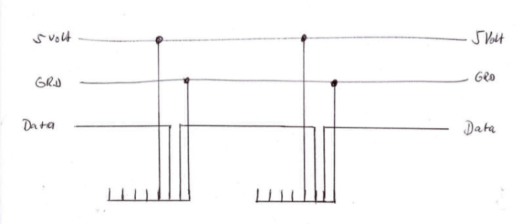
this is what I found out about the uniopi one wire hub.
-
Yes, that seems about right. It's designed to allow multiple RJ45 connectors to share the same 1Wire bus.
We've been toying with the idea of making a Modbus-based active 1Wire hub, but it would be considerably more limited in which devices it can support.