digital output voltage
-
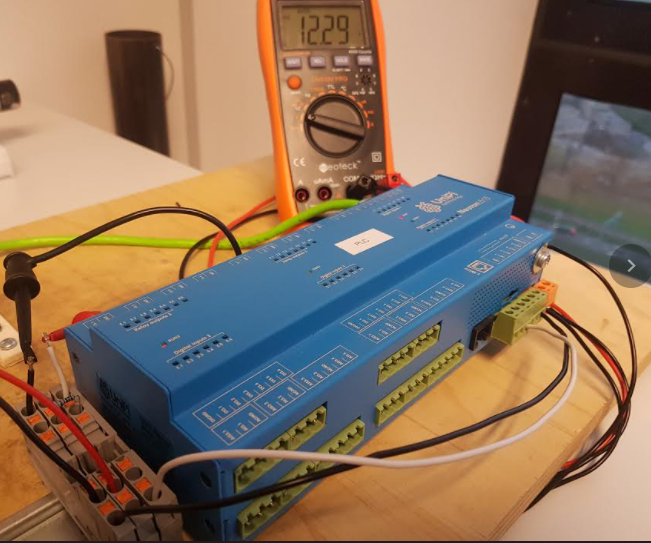
Using a Neuron L513 I'm seeing 0.5V at the digital out pins. Is a higher voltage, eg 5V possible?
At the moment I'm just using the B87 PWM block to generate a 100% duty cycle output. If there's a more straightforward way of always generating a high signal at the digital out (not input dependant) please do let me know.
-
@Martin-Kudláček do you have any advice on how to use PWM properly? I really need some help on this.
I've set up my PWM_cycle and PMW_prescale to meet my frequency and resolution requirements, but this is all useless if the voltage is so low that the driver I'm trying to control can't even see the signal.
The B87_Pulse_Width_Modulation only seems to output True (1) or False (0). I've tried setting the PWM Default value to 5 (guessing this might be voltage), but it doesn't seem to do anything, even if I force the PLC value in the Variable Browser to be 100 (guessing this is the duty cycle). Voltage always sits around 0V. How do I set it to give a 5V output?

-
2nd try at the image:
https://imgur.com/a/PvVDYO2 -
Quick update, I have learned some stuff but not enough to get it working.
Learnings:
- Software PWM (that Mervis B87 fbd block) only works for low frequencies, eg 0.1Hz or less.
- Hardware PWM is different, this is what is addressed in the Advanced mode of digital outputs: PWM tutorial.
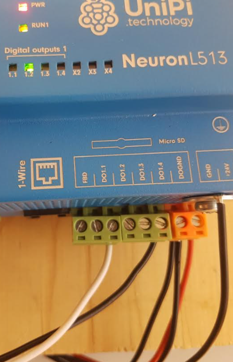
- The digital outputs (which double as digital PWM outputs) are NPN, check out this Neuron 12V digital input forum thread for some info on that.
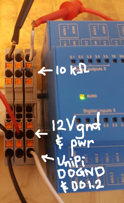
My setup:
To achieve PWM at a frequency of 20kHz, with a resolution of 101 steps, I have set my pwm_cycle to 99, and pwm prescale to 23. I wired up my circuit with a pull up resistor to an external 12V power supply, like this.I was expecting that when the DO pwm is 0% (high impedence) the voltage at P would be 12V, and that when the DO pwm is 100% (shorted to ground) the voltage at P would be 0V. In reality, the voltage at P is always 12V.
What am I missing? It seems like setting the DO pwm value doesn't do anything at all.
-
Hi @mkb,
the picture is probably worth a thousand words: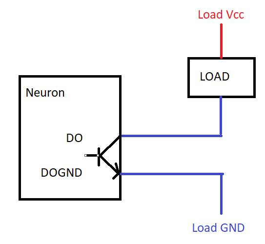
-
Hey @Martin-Kudláček ,
I'm trying to control a motor driver that has three pins:
- DIR (direction) input (10V or 0V),
- PWM (12V or 0V pwm), and
- Ground.
I can't imagine applying pwm switching at the ground will be good for the DIR input, which is why I tried using the pullup resistor as per the image in my previous post.
Is there any other way I can wire this to achieve pwm at the PWM input but not at the DIR input?
-
When I toggle the DO pwm from 0% to 100%, the DO led turns on and off, which makes me think it's working. When I measure resistance between that DO pin and ground though, my ammeter reports infinite resistance for both 0% and 100%.
Is it possible that the DO pwm is broken somehow? I can't see why my wiring schematic wouldn't work otherwise.
-
Hi @mkb, in your schematic, you don't have the DOGND tied to the GND of the 12V PSU. Please start with that.
-
@Martin-Kudláček Ah I left that out of the schematic, but in my setup all of the grounds are common. The power supply ground is indeed connected to the UniPi ground and also the DOGND.
-
@Martin-Kudláček I've set the pwm cycle to 9999 and prescale to 9599 so that I now have a resolution of 10001 steps at a frequency of 0.5Hz (period of 1s).
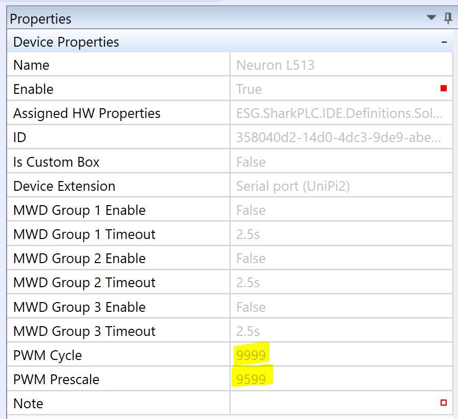
In debugging mode, I've set the PLC value of the PWM pin to 50% (ie 5000).
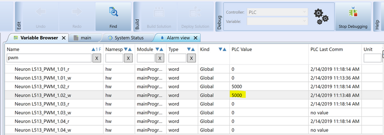
The voltage is staying stubbornly at 12V.
-
-
More info: all of the DOs work in digital out setting. It's only PMW mode that doesn't seem to be working.
@Martin-Kudláček This is an old PLC, I'm not sure how old but the serial number is #37, so we probably bought it in the first year you started selling Neuron L513s. Just before starting this project I updated the OS to 2.3.0.10, and I am using the corresponding Mervis IDE. Could this be a compatibility issue of some sort?
-
Hi @mkb,
I have replicated the configuration (cycle 9999, prescaler 9599, that means resolution 0-10000 with frequency 0.5hz). I put the value 5000 (the 50% for the given resolution) to the PWM variable and was able to read a voltage change across DO1.1 and DOGND with a multimeter. The values changed in 1s interval, which they should with given frequency and duty cycle.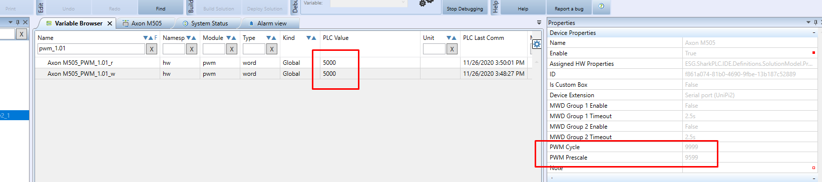
The last piece of SW is called a firmware (FW), which is flashed in the IO boards. Each of the group (you have 3 on the L513) has its own microcontroller running its own firmware. This needs to be up-to-date as well. I looked in our stock system and it shows that your PLC has been shipped with FW 5.5, which is very old.
The firmware cannot be updated via Mervis IDE, but only via SSH connection to the PLC. Please, let's continue via [email protected].
Thanks,
Martin -
@Martin-Kudláček Thanks a ton for all your help with this. I'll send you an email about the firmware update.
-
The problem has been solved by flashing the latest firmware.