Neuron 12V digital input
-
I would like to connect some digital sensors that are powered on 12VDC to an e.g. M303 Neuron (PIR sensors, actually). What would be the proper way to connect these?
I know that for regular push buttons, I need to connect them to the internal power source connection that's available at the DI, but as this is 24VDC, this is probably not possible for my setup. The specs mention that logic level interpretation are ok though (e.g. min 5V for logical 1).
Similar question for digital out btw (although I believe these are open collector outputs, so I should be able to choose my own voltage levels here, right?)
-
Hi @Martijn-Hemeryck,
it depends what type of output your sensor has. Basically there are PNP (sourcing) and NPN (sinking) outputs.- PNP (sourcing) typically outputs supply voltage of the sensor when the sensor is in ON state otherwise it is unconnected (high impedance).
- NPN (sinking) shorts the output against GND when the sensor is ON, otherwise it is unconnected (high impedance).
For example digital outputs on our units are NPN.
If your sensor has PNP output and its supply voltage doesn't exceed 24V, you can typically connect it directly to the UniPi's digital input.
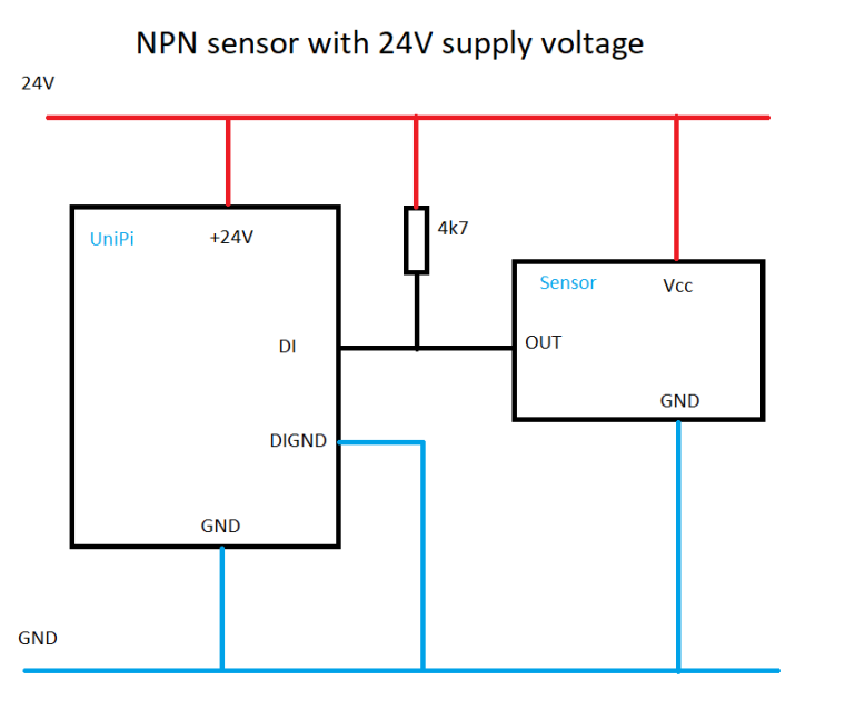
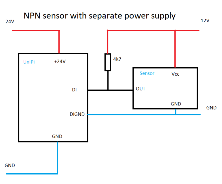
If your sensor has NPN output, that's where it gets a little bit tricky. Digital inputs can only distinguish the ON state (voltage 5-24V). Any other state - be that 0V, short to the ground or high impedance (nothing connected) will result in OFF state. In order to use NPN sensor, you need to define the OFF state by connecting the NPN output to supply voltage via pull-up resistor. And there are two ways how to do it, depending on the supply voltage of the sensor


The pull up resistor will bring the OUT to the level of the supply voltage. In the first example it is 24V, in the second example it is 12V. The GND of the UniPi and the GND of the second power supply may or may not be connected, depending on the level of isolation you need between UniPi and the sensor. But that's another story. But the DIGND has to be connected in both cases.
Martin
-
OK, thx for the detailed feedback (including schematics). Worst-case, I'll just need to add a pull-up resistor, should be fine I suppose. Main issue will probably be just to figure out what kind of setup these sensors use.
-
You can measure the type of sensor quite easily with multimeter. Just connect the sensor to power supply and measure the voltage between OUT and GND. If the voltage changes from 0 to Vcc, then the sensor is PNP type. If not, switch the measurement to resistance. If the resistance changes from OL (open loop) to almost 0 ohm, then the sensor is NPN type.
Martin
-
Ok; took me quite some time, but I just did manage to read out the sensor values.
Leaving this here as future reference; the involved PIR sensor was the Jablotron JS-20 Largo. A small schematic was provided with the sensor out of the box, but the key find for me was that the sensor outputs also need to be wired up to the 12V power source; see adapted schematic and pictures.
Thanks a lot for the schematics, since they really made it possible for me to reverse-engineer the setup.