Hello @Raph7454, all of the IO on the Unipi work the same as other CODESYS devices. Use the device tab to map the IO into your application. The data sheet provides guidance on each device. The package also installs a new application template so that in one step you can create a new UniPi application with all devices installed ( you will just need to add the expansion module).
Regarding how to download, login etc. CODESYS for UniPi is adding device drivers to CODESYS for raspberry pi. There is a large active forum of users on the CODESYS forums. I suggest that for general CODESYS questions you will find answers to most of your questions already posted there.
I
D
Posts made by DavidCozens
-
RE: Novice in CODESYSposted in CODESYS
-
Unipi Neuron fo CODESYS SL 1.0.2.0 availableposted in CODESYS
Version 1.0.2.0 is now available for download in the CODESYS store, this is only a bug fix release fixing a minor defact and updating to later versions of CODESYS and Unipian. The new version is built on CODESYS 3.5.14.0 and is supported on version 1.9 of Unipian. Please see the datasheet in the store for details.
-
RE: UniPi Neuron for CODESYS Temporarily Unavailableposted in CODESYS
A new version is now available in the store updated for CODESYS 3.5.14.0 and supported on a new version of Unipian.
-
UniPi Neuron for CODESYS Temporarily Unavailableposted in CODESYS
With the release of a new version of Unipian (V1.9) and also the release of CODESYS 3.5.14.0 I have had to temporarily remove UniPi Neuron for CODESYS from the CODESYS store. I aim to release a new version by 17/1/19, I will post progress here.
Please accept my apologies for any inconvenience, I am working to provide a solution as soon as possible. -
RE: UniPi Neuron for CODESYS SLposted in CODESYS
Sorry for the confusion. UniPi had removed the UniPian image and so I removed UniPi Neuron for CODESYS from the CODESYS store. I have since been working with UniPi and a new Image for UniPian was released today.
The UniPian image will work with CODESYS 3.5.12.x and the release UniPi Neuron for CODESYS.
3S have also released a new Version of CODESYS which requires a rebuild and retest of UniPi Neuron for CODESYS before the product can be re-enabled in the CODESYS store. I anticipate that this will be released by 17/1/19. I will post here when the new version is available. -
RE: Codesys Neuron Digital Output/Relay Output issueposted in CODESYS
The outputs are assigned as for any IO device in CODESYS. Please check the CODESYS help for how to map IO.
There is also a UniPi Neuron library included in the package which makes it easier to handle the data types which span more than one register. Please see the help for the library in CODESYS. -
RE: CODESYS to Neuron comm problemposted in CODESYS
Hi Ludwigj,
I'm sorry to say but there was a compatibility issue with the version of UniPian that you are using. If you use the version referenced in the datasheet then you should see no problem.UniPi have released a new Version of UniPian V1.9 today that I believe resolves the issue.
regards David
-
RE: Adding groups 2 and 3 on Neuron L513posted in CODESYS
@andré sorry to be so slow responding. Somehow I missed the post. There are instructions in the data sheet on how to use groups 2 and 3.
As a summary getting the IO to work with Group1 was fairly involved, and given that it is identical across all Neuron devices a function block instance is created and the mappings from registers is done automatically. For groups 2 and 3 you will need to map the IO using standard CODESYS features. To make this simpler, all of the Registers and Coils for these groups are named, there are also function blocks provided that will assist with converting between registers and larger data types.
-
RE: Connecting/communicating with a Modbus deviceposted in CODESYS
Hi Oliver,
I’m going to need more detail to be able to help?
What does your configuration look like?
What exactly is the error message and where do you see it?How is the physical device connected and configured?
Is anything sent from the port?
Are there any further device diagnostics?
Unfortunately with all serial communications, including modbus, just one configuration error or wiring error on the master or slave will mean the communications doesn’t work. The process to solve this is really to carefully check every step.
If I was debugging your system, I would first extract as much detail on the error as possible to see if that helps.
Try answering these questions.
Does the master send a modbus request?
Is it at the right baud rate, parity etc?
Does the slave see the request?
Do it’s comms settings match?Is the UID correct?
... -
RE: Connecting/communicating with a Modbus deviceposted in CODESYS
Hi Oliver,
You need a modbus com device for each port you wish to use. Then under those a modbus master device, and then a modbus slave for each slave connected to that port.
The modbus com port needs to be set to com 1 for the first port, 2 for the second..,
So if your slave devices operate with the same serial port settings you could use different modbus addresses for each and connect them to the same port, or put one on each port.
-
RE: Connecting/communicating with a Modbus deviceposted in CODESYS
Hi Oliver,
There is an example of using serial modbus in the Neuron demo application.
Please also have a look at the data sheet regarding installation and serial ports. To be able to use the serial port on a Neuron from CODESYS a one time configuration change is required. If you run the demo application it will make the required change, the data sheet includes details on functions that can be used to configure the serial port.
Please ask if you need more help with this.
-
RE: Neuron L503 - Group 2 analog inputsposted in CODESYS
Hi Oliver,
I believe that the issue is how the inputs are encoded in the modbus registers.
There is an admittedly cryptic explanation of how to read analog inputs from groups other than group 1 in the data sheet.
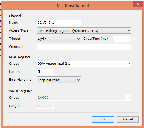
Analog inputs for example are encoded as IEEE754 values in two registers for each input. The Function RegistersToReal can be used to convert the two register values to REALs.
In a little more detail to read a single AI, map a channel to read two registers
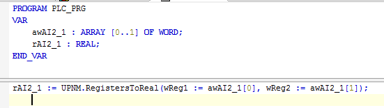
Map those two registers into a pair of words, I tend to use an array, which can be mapped like this

or like this

The code below shows how to convert the registers to a real.
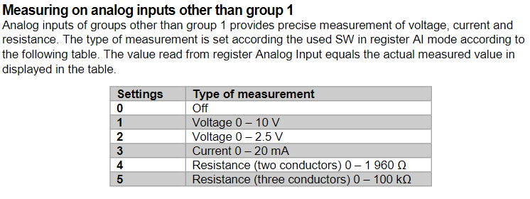
As far as setting the mode of the input, see the Neuron Technical Documentation, it states
To set this value, create a channel like this
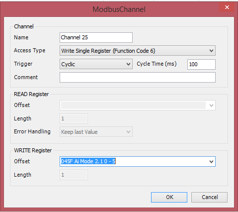 and then map a word with the required value (Be careful that codesys doesn't optimise out the word in your application if it is just declared).
I hope that gets you going - please ask again if you need more assistance.
-
RE: RTC - UniPian - Codesysposted in CODESYS
CODESYS for Raspberry Pi uses the underlying Raspbian (UniPian) operating system to access the RTC. The library DTUtils provides the utilities to access time and date from within CODESYS.
-
RE: UniPI Analog Inputposted in CODESYS
I must have missed this post somehow.
The most likely cause is that the variable that the channel is mapped to has been optimised out because it is otherwise unused.
-
RE: Understanding the Modbus Registers Mapsposted in CODESYS
Hi Oliver,
I'll try to give answers to what I think your questions are.
Firstly an explanation of channels and register mapping.
When a Modbus Channel is configured in CODEYS the length specified is the number of registers to be read or written using a single modbus command. It is more efficient where possible to read multiple registers in one command, this is both runtime efficiency and efficiency of configuration. It is often more efficient to read larger blocks of registers even if you are only interested in a few of the registers. Having configured the channel to read or write the registers, you can then either map all of the registers in one go into an array somewhere in your application, or map just the selected registers that you are interested in.
All of the registers in a Channel are sent in one command. Each register can be mapped separately or all registers in a channel can be mapped as an array.
One the Neuron there registers are defined in groups, and each of the hardware modules on the Neuron has two groups of registers. The channel Group1A reads all 21 registers for Group1 starting at register address 0, these are then mapped into an array inside the Group1 function block. The function block uses the whole block of registers to determine that communications is good, and also to scale analog values etc.
Secondly to deal with the trigger
Most of the time it is preferable to transfer registers on a cyclic basis, however some actions cannot easily be handled on a cyclic basis, for example resetting the counter. On the Neuron you write a 32 bit reset value for the counter, if this was done periodically it would prevent the counter from counting. The solution to this is to use another VAR to trigger the channel to be sent by MODBUS.
CODESYS actually offers three different trigger modes for channels, cyclic (you can choose the rate), trigger (a BOOL value changing from False to True will cause the channel to be sent, or application (The application triggers the channel). Personally, although I have experimented with the application triggering writes, I prefer to use the rising edge trigger).
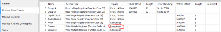
The image above shows where the channel called counter is configured to be sent on a trigger. If you then look in the mapping tab you can see how there is a trigger mapped to a boolean inside the Group1 function block. There are also two registers mapped to an array inside the Group1 function block that contains the value the counter is to be reset to.I hope I have correctly understood your questions. If you have more questions please ask. If the questions are more generic to CODESYS rather than specific to the Neuron I will help, but you may get faster support on the CODESYS forums, there is a large helpful community there.
-
RE: using Modbus overlay in Codesysposted in CODESYS
@tom84
The mA problem is an issue with older hardware. UniPi Neuron for CODESYS will be updated to resolve the issue at the next service release.Please note the issue does not occur on current Neurons. No Neuron products shipped since the release of UniPi Neuron for CODESYS will see this problem.
-
RE: Adding Group 2 and 3 - Neuron L503posted in CODESYS
Hi Oliver,
Please see the datasheet which explains how to map the IO for Groups 2 and 3.
In summary you create variables in your application, and then map from the modbus registers directly to these variables. This is the same as for any modbus device in CODESYS. If the datasheet dowsn't help please see the standard CODESYS help for modbus.
Group1 is the same for all Neuron devices, and is more complex, particularly in regard to scaling Analog values. For this reason a function block is automatically created when the device is added. I would appreciate feedback to determine if doing the same for the other groups would be beneficial, or get in the way.
regards David
-
RE: Reading digital input from switchposted in CODESYS
Hi Oliver,
The POU NeuronL50xGroup1 is a function block automatically created when the IO device for the Neuron is added to the application. It provides easy access to all of the IO and features for Group1, just add the device and then access the IO through the VAR and methods on the function block.
The statements that you have identified are writing to the variables in the function block. these in turn end up mapped to the registers in the channels for the device.
The mechanism of creating channels, and then mapping the values to variables is the standard CODESYS mechanism for modbus devices. UniPi Neuron for CODESYS adds naming for all channels and coils to make this easier. It also adds a function block for Group 1 (which is identical on all Neuron) and performs all of the mapping automatically.
I would be interested in your opinion on this approach of automatically creating a function block with all of the IO mapped. For some users it will be helpful, for others it may not provide what they want. I am considering if I should add the same support for other groups.
For now access to groups 2 and 3 requires you to manually create channels for the IO you wish to access and then map these to VAR in you application. There are some function blocks in the supplied library that may be helpful. This is the same for all CODESYS modbus devices.
There is more detailed help in the datasheet.
-
RE: Multiple Modbus Read Registers Access by an Array of Elementsposted in CODESYS
@mikeardy
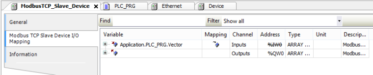
Consider this as an alternative. I've created 500 holding registers
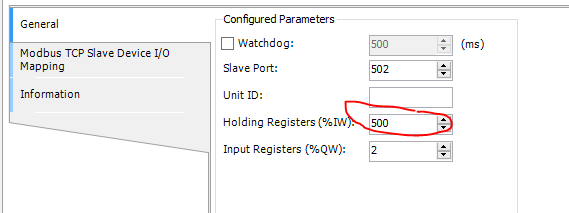
In my program (it could be ina GVL) I have created an addary of 250 UDINT.
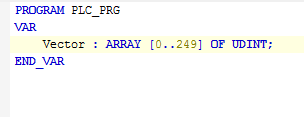
Then I was able to map all of the registers in one go
For generic CODESYS questions I suggest trying https://forum.codesys.com/, for many generic CODESYS questions there will already be an answer posted.
-
RE: using Modbus overlay in Codesysposted in CODESYS
@tom84
That sounds odd, the DAC numbers you mention sound odd to me. So a couple of questions.What load have you got connected on the output?
I should be able top track back and see what is happening if I can see the values of the Group1 registers. Please post images of the values of the Group1A and Group1B mappings page while the system is running with a known rValue.
If you want me to have a quick look at your application then please contact me via https://www.cososo.co.uk/contact/.