1-wire sensor and modbus sensor
-
Hi All,
I have 2 unipi devices with Evok and attached to that some 1-wire sensors via an 8 port hub. Some of those sensors show up as a 1-wire sensors, where others show up as mod-bus devices. I also think that if they show up as modbus devices only one sensors is recognized. (I have multiple connected, only 1 shows up - not in screenshot)
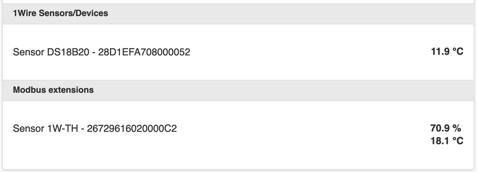
The sensor recognized as 1-wire is a DS18B20 sensor.
The sensor recognized as modbus is a 1W-TH sensor.Can someone help me with this? Is this expected behavior (hope not) or do I need to change something in hard- or software?
Here is a screenshot;
-
Hello @matthijs,
you are right - the 1W-TH sensors are listed in the incorrect category in the WEB Gui. This bug will be fixed in the next release. Other channels (REST API, Websocket, ...) should be OK.
However, the 1W-TH sensor's detection is not affected by this. Can you try the following:
-
Go to http://<your unit IP address>/rest/all and look for the 1wdevice objects - are all sensors connected listed here?
-
Can you describe your application (exact components used and wiring diagram)?
-
-
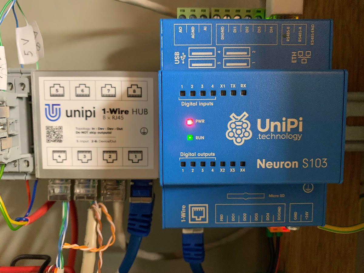
I used my 2nd system to try this. I have 3 sensors connected to a 8 port hub. The sensors work, those are test sensors from my other setup.
@martin_triska said in 1-wire sensor and modbus sensor:
Go to http://<your unit IP address>/rest/all and look for the 1wdevice objects - are all sensors connected listed here?
No, only the sensor I see in the GUI is listed here.
Can you describe your application (exact components used and wiring diagram)?
It's fairly simple, a std UTP cable between my Unipi and the 8 port HUB, and 3 device from there;
I do have to note that I have sensors from SEDtronic directly too, since they can come coated. The first sensor in line is of that type for outdoor temp / hum measurement.
-
Hello @matthijs,
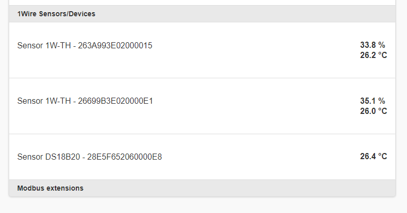
there seems to be something wrong with the HW. I just tried to connect two 1W-TH sensors and one DS18B20 via the hub and there is everything OK in the Evok control panel:
Do you have tied data lines (RJ45 pins 6 and 7) together on the 1W-TH sensors?
Please read the related section on our KB.
You can also upgrade the Evok package to get the 1W devices listed under the right category:
apt update && apt install evok=2.3.5.test.20201112163426 -
@martin_triska said in 1-wire sensor and modbus sensor:
have tied data lines (
No, I don't believe I did. Is the order of the wires relevant? So if I would switch the data lines on a sensor, would that explain this behavior?
-
Hello @matthijs,
the order of two data wires on the 1W-TH sensor terminal can be random as both data lines are interconnected together here. All sensors connected to the hub have "daisy-chain" topology (not a star topology!) - if data lines are not coupled in sensor, data cannot pass-through to the rest of the network - this is why you see only the first of 1W-TH sensors.
-
@martin_triska I tried connecting the modules via this drawing;
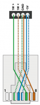
So 2 wires to + and 2 wires to GND and I needed to change wires to other ports from my previous situation. Does not show up at all now anymore now. :-(
Also, I do not understand where to bridge the wires to make it a daisy chain. Do i just need to place a wire on the sensor between 1W> and 1W< to loop it?
Am I following the right picture?
-
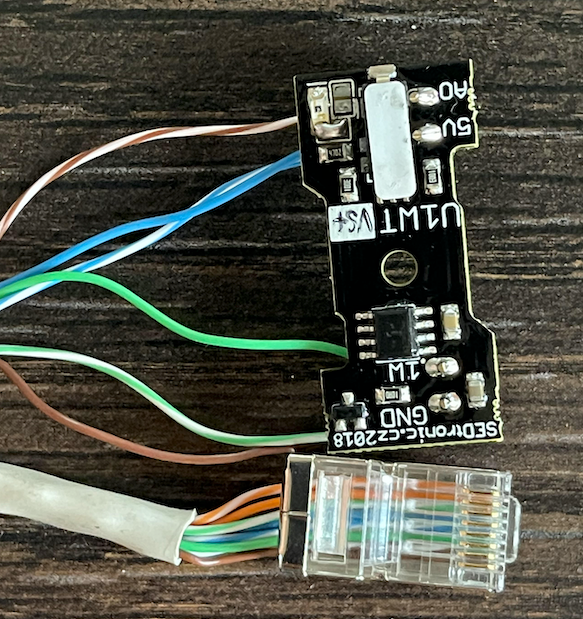
Here is a picture
-
Hello @matthijs ,
you do not need to add any additional wire to connect data wires together on 1W-TH sensors. Terminals 1W> and 1W< are already interconnected internally. The SEDtronic sensor on the picture does not have these terminals -> in this case, you have to tie the wires manually ON THE SENSOR. According to the photo, you have to connect dark-green and light-brown wires together ON THE PCB.
Please let me know if the problem persists.
-
@martin_triska said in 1-wire sensor and modbus sensor:
in this case, you have to tie the wires manually ON THE SENSOR. According to the photo, you have to connect dark-green and light-brown wires together ON THE PCB
Yes, that did the trick!
Thanks for the education and superb support here Martin. Really enjoy using your products.