Read Coil Analogic Output M103
-
@mohamed-dounnani The device (analog output) cannot be turned off, but if you want it to output 0V, then save the value 0 to the "Analog Output 1" register
-
How can i Turn Luminosity to 0 or simulate that is off? Because if I put 0V, decrease luminosity but not completely
There is any way to do accomplish that? -
@mohamed-dounnani Can you please describe what are you trying to achieve? So far we were discussing analog outputs, which I am unable to connect with luminosity. A schematics of your setup or list of devices which you want control would be heplful. Thank you!
-
I have a 0-10V Led. I need to be able to turn it Off and On with a certain luminosity. I choose a Vdesired for example 5V and the luminosity decrease, now i need to turn it off when necessary. But when I insert a 0V in Vdesired luminosity decrease at 10% about but never turn off.
-
@mohamed-dounnani You can simply verify the functionality with multimeter by measuring the output voltage between AO and AGND. With register "Analog Output 1" = 0 the output voltage should be 0V.
-
@martin-kudláček "With register "Analog Output 1" = 0 the output voltage should be 0V". I do that but still the light is on.
"You can simply verify the functionality with multimeter by measuring the output voltage between AO and AGND. " What I accomplish with this operation?
-
@mohamed-dounnani You will verify, that the data you set in the Modbus registers really do what you are intending to do.
I guess you use some LED 0-10V dimmer, similar to this one:
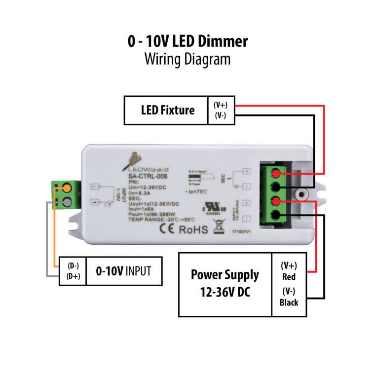
If the D- and D+ are unconnected or shorted (connected together) the LED should be off. Is this happening to you?
-
They are connected. I can't misure now the V in output, there is a way to be able to turn led completely off?
-
@mohamed-dounnani
Basically there can be two things wrong in your setup and in order to help you I need you to test them separately.- Verify the output voltage
- Disconnect everything from the AO and AGND
- connect a voltmeter (or multimeter set to DC voltage measurement) between AO and AGND (positive / red test lead to AO, negative / black test lead to AGND)
- set the desired voltage via Modbus registers and verify the actual output voltage
- set the voltage to 0V via Modbus registers and verify that the output voltage is 0V
- Verify the functionality of the LED dimmer
- connect the LED to the dimmer
- connect the power supply to the dimmer
- leave the 0-10V input unconnected
- the LED should be off.
Please proceed with both suggestions and get back to me with the result. Otherwise it is almost impossible to help you.
Thank you for understanding,
Martin -
"Verify the functionality of the LED dimmer
connect the LED to the dimmer
connect the power supply to the dimmer
leave the 0-10V input unconnected
the LED should be off."I leave the 0-10V input unconnected from unipi and led are On like 100% Luminosity.
"Verify the output voltage
Disconnect everything from the AO and AGND
connect a voltmeter (or multimeter set to DC voltage measurement) between AO and AGND (positive / red test lead to AO, negative / black test lead to AGND)
set the desired voltage via Modbus registers and verify the actual output voltage
set the voltage to 0V via Modbus registers and verify that the output voltage is 0V"When I set 0V via Modbus multimeter reveals like 1.066 Volt and not 0 volt.
-
Ok @mohamed-dounnani, now we are getting somewhere!:)
For the first part (verifying the output voltage), did you try to set the voltage to e.g. 5 volts and measured the actual output as well? What was the result? I need to be extra sure, that your way of saving data into the Modbus registers really works. It's not that I don't trust you, but it isn't really straightforward:)
Thanks!
Martin -
If i set 6 Volt the result is 2294.784382284382
-
@mohamed-dounnani I am sorry, but I don't understand. You should calculate a value using the formula and the result should be between 0 - 65535. Then you should write the value into the Analog Output 1 Modbus register. By doing this, the internal circuit in the UniPi controller will set the desired output voltage between the screw connectors AO and AGND. Then you should measure this value with multimeter to verify if the actual output is equal to the desired voltage you wanted to set. Have you done so please?
Martin
-
I calculate value using formula and when i select 6V that is my desired volt, that formula produce 2294. I take the result and I write it to Analog Output 1 Modbus register
When I select 0V, the formula produce 0, but when i measure the output with multimeter i measure 1.066 V
-
Ok @mohamed-dounnani, and what happens, when you write the value 2294 into the Analog Output 1 Modbus Register? What is the actual ouput voltage on the connector?
-
7 approximately
-
Ok @mohamed-dounnani, I tested it on my S103, which is basically the same as yours. Mine works with the same procedure I told you. I wrote value 2178 and got 5.678V as expected. When I write 0, the output is 0V.
To investigate further, I need several informations from you:
- What SD card image do you use?
- How do you communicate with the ModbusTCP server?
- If you write 0 to the register 2, what value from the register you read back?
Thanks in advance,
Martin -
I use Raspbian Stretch
I communicate with node.js using a npm library.
If i wrote 0 i receive 0 as value -
Ok @mohamed-dounnani, let's try one last thing. Can you read the value of register 1019? That's the settings of the Analog Output. It should be 0, which stands for Voltage output. 1 means Current output and 3 means Resistance measurement.
Thank you,
Martin -
I receive 0, so is for Voltage Output