1 Wire problems
-
Hi,
I have a 3m 1Wire network on an Unipi 1.1 with 5 temps sensors.
I can't have them to work. I check the wiring.
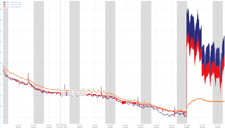
This is what Mervis find:
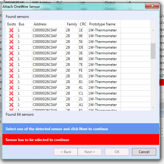 .
.
Do you know this issue ? -
Hi,
After many test and wiring, My 1-Wire network can't exeed 1m to be stable; with one or more sensors it's the same.
I'm using cat 5e shielded with brown to gnd, white/blue to Vcc and white/brown to Data.
I olso test to put the shield on the installation ground (the earth).
My sensors are DS18B20.
The Vcc is about 4,80V.
When we have 5 sensors, is it necessary to put pull-up resistor and where?
Next step is to plug my oscilloscope to Vcc and Data pin to check weldings.
Does I'm doing something wrong or does my Unipi 1-wire chips (master or esd) have a problem ? -
Hi,
I have some things to understand...
I can see (first picture) on the RJ45 connector, there are no 3 but 6 wires. 7 and 6 are the same pair, 3-6 and 4-5 too, so data lines are always twisted with the ground.
And now (second picture), if I well understand, pin 6 and 7 are not the same on the Unipi, one for write (pin7) and one for read (pin6). Is that true? So am I to connect sensors to the pin 6 or 7 only or to 6 and 7 together when I'm not using a HUB but weldings ?
Olso, is your Hub active (mean with DS chips inside) ?
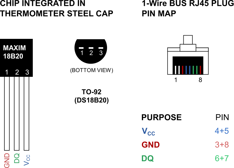
 image url)
If you are here, thank for your time to read my posts.
-
Hi,
Ok, now my one wire network is working for a few minutes.
I have put 4+5 together, 3+8 and 6+7, but I have inserted a 150ohm resistor to the data pin of each branch, one branch for one sensor in the middle (1.5m) and one for the star "branch" to the end at 3m.
According to the specification, 150ohm resistor is not suposed to work for the DS2482-X but it's actualy the only way I found to make it works (for a few minutes) whereas without resistor no sensor is found.Is there a way to modify the DS2482-x configuration register to test diferent PullUp options ?
So the 1 wire is very important for me, it controls solar heating panels and boiler, without this working it's realy a problem.
Thanks to help me to get it working.
-
@Giamba The purpose of DQ lines to be on 6+7 is to serialize the topology as much as possible. So from UniPi the DQ line is only on 7, than it goes to HUB/Sensor, from which it returns on 6, then the HUB switches it to 7 for the next Sensor/HUB and so on...
In the Mervis image, the only active pull up is enabled by default. The SPU (used only when the the sensors use parasitic power) can be enabled, but is not needed because all the sensors should be connected to the VCC.
Check that all sensors have VCC connected OK so none of the network uses parasitic power.
-
Hi @tomas_hora,
So this is the chart I get of few hours with some unusual peaks and a unfortunate no signal blackout at the end for a couple of minutes.
Could you please provide me a chart that shows on a long term basis multiple 1wire sensors curves to make sure that the product (sensors and hub) you sold on you website are reliable.
Thanks in advance.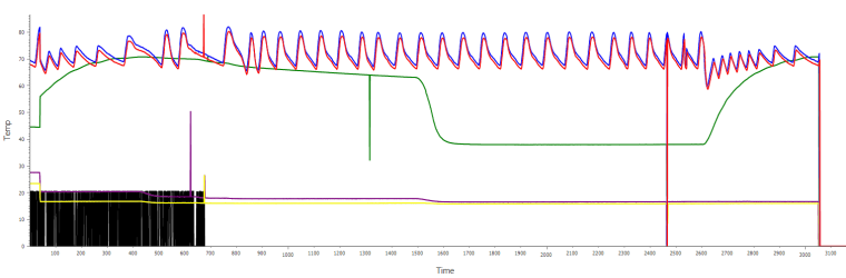
-
@Giamba This sometimes happens, I recommend using a filtering function block for each temperature sensors. Something like this, this is a old filter that one of our customers used:
FUNCTION_BLOCK check_1w_temp
(*
EXTENDS //base type
IMPLEMENTS //interface type list
*)
	VAR NON_RETAIN
		(* add local variables here *)
		first_run:		bool:= TRUE;
		prev_temp:		real:= 999.99;
		filter: 		LIB.CORE.V1_0.B86_FILTER;
	END_VAR
	VAR_INPUT
		(* add in variables here *)
		actual_temp:			real:= 0;
		err_diff:				real:= 5;
		por_diff:				real:= 1;
		filter_const:			real:= 60;
		min_temp_allowed:		real:= -55;
		max_temp_allowed:		real:= 125;
	END_VAR
	VAR_OUTPUT
		outtemp:			real;
		err_measure:		bool:=FALSE;
		(* add out variables here *)
	END_VAR

(*function block body*)

//first run
IF first_run THEN
	outtemp:=actual_temp;
	prev_temp:=actual_temp;
	err_measure:=FALSE;
	first_run:=FALSE;
	RETURN;
END_IF;

//filter out impossible values
IF actual_temp > max_temp_allowed OR actual_temp < min_temp_allowed THEN
	outtemp:=prev_temp;
	err_measure:=TRUE;
	RETURN;
END_IF;


//filter out POR 85.0C errorrs
IF abs(prev_temp-actual_temp)>=por_diff AND actual_temp = 85.0 THEN
	err_measure:= TRUE;
	outtemp:=prev_temp;
//and filter measurre errors
ELSIF abs(prev_temp-actual_temp)>=err_diff THEN
	err_measure:=TRUE;
	outtemp:=prev_temp;
	//prev_temp:=actual_temp;
ELSE
	outtemp:=actual_temp;
	prev_temp:=actual_temp;
	err_measure:=FALSE;
END_IF;

//apply analog filer -> smooth the signal

IF err_measure = FALSE AND filter_const > 0 THEN
	filter(IN:= actual_temp, INDT:= filter_const, OUT=>outtemp);

END_IF;

END_FUNCTION_BLOCK
And the graph: